The Idea:
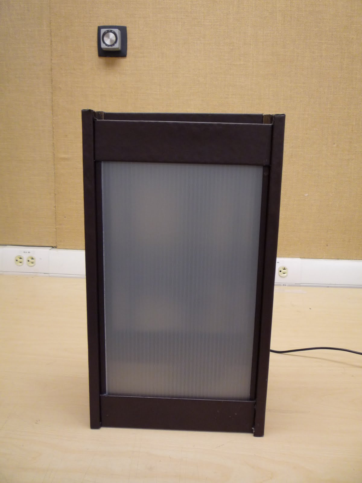
When we were introduced to this project as the "Lamp Monster" I knew I wanted my project to grow when it got angry, and what would piss you off more than getting electricuted by a battery? Essentially, what I came up with was a lamp fixture that opens up to reveal a smaller compartment which houses an LED light source. The LEDs are controlled using a photoresistor allowing for the lights to get brighter as the surrounding environment gets darker (and vise versa) While trying to figure out how to make this thing open and close I considered small gear system attached to a servo motor or a some kind of pully system but it seemed overly complicated for such a simple function. After discussing the project with my brother, a mechanic, we determined that this process could be simplified by using a window motor and regulator assembly from a car.
The Materials:
- Arduino Microcontroller
- Auto Window Motor and Regulator Assembly
- 10 LEDs
- 12v battery
- Photoresistor
- 10k Ohm resistor
- Up/Down toggle switch
- 18 ga. wire for motor
- 24 ga. wire for lights
- Two 1/4" x 1" machine bolts
- Two 1/4" x 1" coupling nuts
- Two 1/4" x 1" washers
- Approx. 3 sheets of 28" x 40" double ply chip board
Step One:
The first step to contructing this project was building a case that would house the motor and regulator. The housing is composed of two pieces, a main lower case where the motor and regulator will be mounted and an upper light compartment that will be pushed and pulled by the motor. Using a laser cutter and some chip board I cut out the individual pieces for the vertical and horizontal supports, then laminated those pieces until they were four plies thick. Once the glue had cured I assembled the upper and lower portions seperately. On the lower portion of the case I located the mounting studs on the horizontal bracing and driled 1/4" holes for the machine bolts. After attaching the coupling nuts to the mounting studs on the regulator I attached the entire assembly to the lower portion of my case.

Step Two:
Now that the motor and regulator assembly were in place I can wire in the switch. Initially, I wanted to have the motor controlled by the arduino board using a proximity sensor (if you got within five feet it would open up otherwise it would close) but I ran into some trouble because the window motor is multidirectional. Whether the motor moves up or down depends on the direction in which the current is flowing. I was able to give dedicated power and ground through the arduino, but I could not figure out how to switch between the two. I hope to revisit this with some assistance but eventually, I ended up using a two way up/down switch to control motion.

Using the two way switch allowed me to reverse the flow of current at will, but the wiring was a little weird. The two center leads go to the main power and ground source. The top and bottom leads are then crossed and spliced (ie. top left and bottom right leads are wired seperately and then spliced together. 2 input, 1 output). Now there are a total of four wires the two from the center that will connect to the battery and the two top and bottom wires that will connect to the motor. The wiring is a little unrefined at the moment but once everything is connected you should be able to move the motor using the switch.
Step Three:
Once the motor was in place and operational I created two light bars using five LED's each. The LED's were wired in series so they would terminate in a single positive and single negative lead per light bar. I made sure to leave enough extra wire as these light bars will be attached to the upper portion of the case and will be moving up and down roughly 12". One of the problems I had once the LEDs were installed was controlling the brightness. I felt as though the lights were underpowered and were not shining as brightly as they could.

Step Four:
Now that the wiring was pretty much complete I created two face plates one for the upper and lower case. I created a simple face plate using some basswood and corrugated plastic but you can use any number of materials and turn it into a type of infill excercise. I plan on playing around with this part alot more.

Step Five:
Now that everything has been assembled I created the following circuit to controll the LEDS through the Arduino board using a photosensor.
- LED 1 and LED 2 connected from digital pin 9 to ground
- Photoresistor attached from analog pin 0 to ground
- 10k ohm resistor attached from analog pin 0 to ground

Step Six:
Once the circuit has been created I used the following code to control the lights
//Program to control LED through Photoresistor
//brightness specified by the value of the analog input
// as the environnment gets darker the LEDs get brighter
int val = 0; // variable used to store the value coming from the sensor
int LED = 9; // defines digital pin 9 as LED
void setup() {
pinMode(LED, OUTPUT); // defines LED pin as output
}
void loop() {
val = analogRead(0);// read the value from the sensor
analogeWrite(LED, 15000/val); //makes brightness of LED dependant on analog input
// as "val" increases power output decreases
delay(10); // stops the program for a period of time
}
This code worked pretty well but there were a couple things I couldnt figure out. I wanted to install a button so that when the lamp was fully open it would hold this button and initiate the lights until it is let go however I couldnt get the button to work with the photosensor the way I wanted it to. In the end I eliminated the button for the sake of time but it is something I hope to revisit with some assistance.

No comments:
Post a Comment