Tuesday, June 29, 2010

Hacking a Light Toy

So after much frustration with my first attempt I decided to hack a toy instead of making something from scratch. The toy, shown below, just had a push button before, but I wanted to make it come on when the lights went off.

IMG_3334

IMG_3335

After breaking open the toy I popped out a piece from the back and slipped the wires out of the new hole.

IMG_3344

Before adding a sensor I wanted to make sure I could hack it and ran it with a simple blink code.
After doing this I was able to manipulate the function by making it strobe on and off. Success!

IMG_3383

Now it's time for the photo resistor.

IMG_3385

I removed the button to replace it with the photo resistor.

IMG_3388

Set the resistor with hot glue.

IMG_3389

Solder some wires to it.

IMG_3390

Pull out the wires.

IMG_5576

Wire it up to the arduino.

IMG_5578

Lights on...

IMG_5583

Lights off...

The code I used is very simple. It's a combination of the example blink and button.

Here's the code:

/*
photo resistor as a Button

Turns on and off anything connected to digital
pin 13, when pressing a pushbutton attached to pin 2.


The circuit:
* LED attached from pin 13 to ground
* pushbutton attached to pin 2 from +5V
* 10K resistor attached to pin 2 from ground

* Note: on most Arduinos there is already an LED on the board
attached to pin 13.


created 2005
by DojoDave
modified 17 Jun 2009
by Tom Igoe

http://www.arduino.cc/en/Tutorial/Button

modified june 2010
by Richard Meacham
http://interactivesquared.blogspot.com/
*/

// constants won't change. They're used here to
// set pin numbers:
const int buttonPin = 2; // the number of the pushbutton pin
const int ledPin = 13; // the number of the LED pin

// variables will change:
int buttonState = 2000 ; // variable for reading the pushbutton status.

void setup() {
// initialize the LED pin as an output:
pinMode(ledPin, OUTPUT);
// initialize the pushbutton pin as an input:
pinMode(buttonPin, INPUT);
}

void loop(){
// read the state of the pushbutton value:
buttonState = digitalRead(buttonPin);

// check if the pushbutton is pressed.
// if it is, the buttonState is HIGH:
if (buttonState == HIGH) {
// turn LED on:
digitalWrite(ledPin, HIGH); // set the LED on
delay(500); // wait for a second
digitalWrite(ledPin, LOW); // set the LED off
delay(250); // wait for a second
}
else {
// turn LED off:
digitalWrite(ledPin, LOW);
}
}

And the wiring diagram:

button

Monday, June 21, 2010

Brain Storm

So I've been working on a list of ideas that I thought might be fun some better than others;

Board of balloons that inflate to reflect the location of a person

Series of fans that move to blow air away from people

Maybe we integrate the idea of a projected touchscreen with sound so that it projects an image on the floor and when you step in a certain area it produces some sort of sound

Some type of audio instructions that tell people how to interact with the project, then when they do it something happens

Some type of mirror mirror on the wall looking thing that begs to be freed from the "mirror prison" then when you touch it, it screams to leave it alone

Multitouch Surface

I've been looking at precedents for this final installation project and was intrigued by this multitouch surface. Its a little bit on the complicated side but I think we can do within our time constraints. Essentially it is a touchscreen that is attached to a computer in such a way that you dont need a mouse or keyboard. Check out the website below to see some of the applications.

Its an interesting project and has the potential to be extremely interactive but its also kind of boring in the sense that it is competely digital; It doesnt move, there arent any interesting mechanics or cool materials. Anyhow, check it out and let me know what you think. Also shoot any ideas you guys might have my way.

http://www.maximumpc.com/article/features/maximum_pc_builds_a_multitouch_surface_computer?page=0%2C0

Wednesday, June 16, 2010

Photos from our first Presentation

Arduino Resources

Take a look at this video


Then take a look at this intro to coding [pdf]. It covers the basic of code well.

Next take a look over at adafruit's tutorial that walks through each line of the basic blink sketch.

Remember to have fun!

The Idea


The Idea:

When we were introduced to this project as the "Lamp Monster" I knew I wanted my project to grow when it got angry, and what would piss you off more than getting electricuted by a battery? Essentially, what I came up with was a lamp fixture that opens up to reveal a smaller compartment which houses an LED light source. The LEDs are controlled using a photoresistor allowing for the lights to get brighter as the surrounding environment gets darker (and vise versa) While trying to figure out how to make this thing open and close I considered small gear system attached to a servo motor or a some kind of pully system but it seemed overly complicated for such a simple function. After discussing the project with my brother, a mechanic, we determined that this process could be simplified by using a window motor and regulator assembly from a car.

The Materials:
  • Arduino Microcontroller
  • Auto Window Motor and Regulator Assembly
  • 10 LEDs
  • 12v battery
  • Photoresistor
  • 10k Ohm resistor
  • Up/Down toggle switch
  • 18 ga. wire for motor
  • 24 ga. wire for lights
  • Two 1/4" x 1" machine bolts
  • Two 1/4" x 1" coupling nuts
  • Two 1/4" x 1" washers
  • Approx. 3 sheets of 28" x 40" double ply chip board
Step One:

The first step to contructing this project was building a case that would house the motor and regulator. The housing is composed of two pieces, a main lower case where the motor and regulator will be mounted and an upper light compartment that will be pushed and pulled by the motor. Using a laser cutter and some chip board I cut out the individual pieces for the vertical and horizontal supports, then laminated those pieces until they were four plies thick. Once the glue had cured I assembled the upper and lower portions seperately. On the lower portion of the case I located the mounting studs on the horizontal bracing and driled 1/4" holes for the machine bolts. After attaching the coupling nuts to the mounting studs on the regulator I attached the entire assembly to the lower portion of my case.


Step Two:

Now that the motor and regulator assembly were in place I can wire in the switch. Initially, I wanted to have the motor controlled by the arduino board using a proximity sensor (if you got within five feet it would open up otherwise it would close) but I ran into some trouble because the window motor is multidirectional. Whether the motor moves up or down depends on the direction in which the current is flowing. I was able to give dedicated power and ground through the arduino, but I could not figure out how to switch between the two. I hope to revisit this with some assistance but eventually, I ended up using a two way up/down switch to control motion.


Using the two way switch allowed me to reverse the flow of current at will, but the wiring was a little weird. The two center leads go to the main power and ground source. The top and bottom leads are then crossed and spliced (ie. top left and bottom right leads are wired seperately and then spliced together. 2 input, 1 output). Now there are a total of four wires the two from the center that will connect to the battery and the two top and bottom wires that will connect to the motor. The wiring is a little unrefined at the moment but once everything is connected you should be able to move the motor using the switch.

Step Three:

Once the motor was in place and operational I created two light bars using five LED's each. The LED's were wired in series so they would terminate in a single positive and single negative lead per light bar. I made sure to leave enough extra wire as these light bars will be attached to the upper portion of the case and will be moving up and down roughly 12". One of the problems I had once the LEDs were installed was controlling the brightness. I felt as though the lights were underpowered and were not shining as brightly as they could.


Step Four:

Now that the wiring was pretty much complete I created two face plates one for the upper and lower case. I created a simple face plate using some basswood and corrugated plastic but you can use any number of materials and turn it into a type of infill excercise. I plan on playing around with this part alot more.


Step Five:

Now that everything has been assembled I created the following circuit to controll the LEDS through the Arduino board using a photosensor.

  • LED 1 and LED 2 connected from digital pin 9 to ground
  • Photoresistor attached from analog pin 0 to ground
  • 10k ohm resistor attached from analog pin 0 to ground

Step Six:

Once the circuit has been created I used the following code to control the lights

//Program to control LED through Photoresistor
//brightness specified by the value of the analog input
// as the environnment gets darker the LEDs get brighter

int val = 0; // variable used to store the value coming from the sensor
int LED = 9; // defines digital pin 9 as LED

void setup() {
pinMode(LED, OUTPUT); // defines LED pin as output
}

void loop() {
val = analogRead(0);// read the value from the sensor
analogeWrite(LED, 15000/val); //makes brightness of LED dependant on analog input
// as "val" increases power output decreases
delay(10); // stops the program for a period of time
}

This code worked pretty well but there were a couple things I couldnt figure out. I wanted to install a button so that when the lamp was fully open it would hold this button and initiate the lights until it is let go however I couldnt get the button to work with the photosensor the way I wanted it to. In the end I eliminated the button for the sake of time but it is something I hope to revisit with some assistance.

Tuesday, June 15, 2010

Distance Sensing Lamp

I built is quick demonstration piece for class today. I wanted to show how you can use a RGB led along with a proximity sensor to create a dynamic experience. I built a lamp that changes colors the closer someone stands to it.

 
High Power LED and Proximity Sensor in the Box

Light is blue, something is close to the sensor

Light is pink, something is nearby, but not as close

The arduino wired up

Close up of the sensor

Here is the code being used
int proxypin1 = 4;

int common_anode = 8;
int red_pin = 9;
int blue_pin = 11;
int green_pin = 10;

int red_min = 0;
int red_max = 255;

int blue_min = 0;
int blue_max = 180;

int green_min = 0;
int green_max = 180;

void hsv_to_rgb(float h, float s, float v, unsigned char *rc, unsigned char *gc, unsigned char *bc) {
int h_i = ((int)(h/60)) % 6;

float f = (h/60) - (int)(h/60);

float r,g,b;

float p = v * (1.0 - s);
float q = v * (1.0 - f*s);
float t = (1.0 - (1.0 - f)*s);

switch(h_i) {
case 0:  r = v; g = t; b = p; break;
case 1:  r = q; g = v; b = p; break;
case 2:  r = p; g = v; b = t; break;
case 3:  r = p; g = q; b = v; break;
case 4:  r = t; g = p; b = v; break;
case 5:  r = v; g = p; b = q; break;
}

*rc = red_max - (char)((red_max - red_min)*r);
*gc = green_max - (char)((green_max - green_min)*g);
*bc = blue_max - (char)((blue_max - blue_min)*b);
}

void setup() {
pinMode(common_anode, OUTPUT);
digitalWrite(common_anode, HIGH);

pinMode(red_pin, OUTPUT);
digitalWrite(red_pin, HIGH);

pinMode(green_pin, OUTPUT);
digitalWrite(green_pin, HIGH);

pinMode(blue_pin, OUTPUT);
digitalWrite(blue_pin, HIGH);

pinMode(proxypin1, INPUT);

Serial.begin(9600);
}

float h = 0.0;
float s = 1.0;
float v = 0.8;

int pulse;
int distance1;
byte maxdistance = 250;
void loop() {

  unsigned char r,g,b;
  
  for(int i=0;i<2;i++){
    pulse = pulseIn(proxypin1, HIGH);
    distance1 += pulse/147;
  }
  distance1 /= 2;
  Serial.print(distance1,DEC);
  Serial.print(10,BYTE);

hsv_to_rgb(map(constrain(distance1,6,maxdistance),6,maxdistance,0,359),s,v, &r,&g,&b);
distance1 = 0;
//analogWrite(red_pin, 0);


analogWrite(red_pin, r);
analogWrite(green_pin, g);
//analogWrite(green_pin, 0);
analogWrite(blue_pin, b);
//analogWrite(blue_pin, 255);

delay(100);
}


Light Snake Failure

Before I succeeded I had several failures. My first attempt at creating a light project involved stripping a coaxial cable to its individual parts.

Coaxial-Cable

I then dissected the internal cable into segements to use as a power wire .

Light Snake

The next step was to solder an led to each segment and encase it in hot glue while leaving the ground exposed

Light Snake1

I attempted to use the wire mesh as a ground casing, but failed. It couldn't carry the current well enough.

Light Snake2

I cut off the mesh and tried to wrap a braided copper wire (stolen from a lamp by the dumpster) to use as the ground instead. It worked!

Light Snake4

I wasn't happy with the brightness of the led's, so I gave them nine volts. "crackle pop pip zap" dead.....time to try again

Monday, June 14, 2010

Frustrated

Grrrr! this is frustrating.... I fried my first attempt at an interactive light project,(gave it too much power and shorted out the leds). Now my servo wont work right. It sounds like it wants to turn but then doesn't, it just growns. This was fun now I'm frustrated.

Wednesday, June 9, 2010

First Project

My first project I've been working on is playing with a RFID Card Reader. I hope to build a device that can unlock a door when a valid card is read.

Here is the Code I'm using

/**
* RFID Access Control Single
*
* This project implements a single stand-alone RFID access control
* system that can operate independently of a host computer or any
* other device. It uses either an ID-12 RFID reader module from ID
* Innovations or an RDM630 RFID reader module from Seeed Studio to
* scan for 125KHz RFID tags, and when a recognised tag is identified
* it toggles an output for a configurable duration, typically 2
* seconds. The output can then be used to control a relay to trip an
* electric striker plate to release a door lock.
*
* Because this project is intended to provide a minimal working system
* it does not have any provision for database updates to be managed
* externally from a host, so updates to the accepted cards must be
* made by changing the values in the code, recompiling the program,
* and re-uploading it to the Arduino. It does however report card
* readings (both successful and unsuccessful) via the serial
* connection so you can monitor the system using a connected computer.
*
* Some of this code was inspired by Tom Igoe's excellent RFID tutorial
* which is detailed on his blog at:
* http://www.tigoe.net/pcomp/code/category/PHP/347
* And also from the ID-12 example code on the Arduino Playground at:
* http://www.arduino.cc/playground/Code/ID12
*
* Copyright Jonathan Oxer 
* http://www.practicalarduino.com/projects/medium/rfid-access-control

* Code From http://github.com/practicalarduino/RFIDAccessControlSingle/blob/1d6c42ae53e199269acb0234ad6c3dc784c51f41/RFIDAccessControlSingle.pde
*/

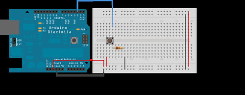
// Set up the serial connection to the RFID reader module. The module's
// TX pin needs to be connected to RX (pin 4) on the Arduino. Module
// RX doesn't need to be connected to anything since we won't send
// commands to it, but SoftwareSerial requires us to define a pin for
// TX anyway so you can either connect module RX to Arduino TX or just
// leave them disconnected.
#include <SoftwareSerial.h>

 
#define rxPin 4
#define txPin 5

// Create a software serial object for the connection to the RFID module
SoftwareSerial rfid = SoftwareSerial( rxPin, txPin );

// Set up outputs
#define strikePlate 12 // Output pin connected to door lock
#define ledPin 13 // LED status output
#define unlockSeconds 2 // Seconds to hold door lock open

// The tag database consists of two parts. The first part is an array of
// tag values with each tag taking up 5 bytes. The second is a list of
// names with one name for each tag (ie: group of 5 bytes).
char* allowedTags[] = {
  "460071B072", // Tag 1
  "04146E8BDD", // Tag 2
  "0413BBBF23", // Tag 3
};

// List of names to associate with the matching tag IDs
char* tagName[] = {
  "Matthew Doll", // Tag 1
  "Hugh Blemings", // Tag 2
  "Dexter D Dog", // Tag 3
};

#define redPin 9
#define greenPin 10
#define bluePin 11


#include <Servo.h> 
Servo doorLock;

// Check the number of tags defined
int numberOfTags = sizeof(allowedTags)/sizeof(allowedTags[0]);

int incomingByte = 0; // To store incoming serial data

/**
* Setup
*/
void setup() {
  pinMode(redPin, OUTPUT);
  pinMode(greenPin, OUTPUT);
  pinMode(bluePin, OUTPUT);
  digitalWrite(redPin, LOW);
  digitalWrite(greenPin, HIGH);
  digitalWrite(bluePin, HIGH);

  Serial.begin(38400); // Serial port for connection to host
  rfid.begin(9600); // Serial port for connection to RFID module

  doorLock.attach(2);

  Serial.println("RFID reader starting up");
}

/**
* Loop
*/
void loop() {
  byte i = 0;
  byte val = 0;
  byte checksum = 0;
  byte bytesRead = 0;
  byte tempByte = 0;
  byte tagBytes[6]; // "Unique" tags are only 5 bytes but we need an extra byte for the checksum
  char tagValue[10];

  // Read from the RFID module. Because this connection uses SoftwareSerial
  // there is no equivalent to the Serial.available() function, so at this
  // point the program blocks while waiting for a value from the module
  if((val = rfid.read()) == 2) { // Check for header

    bytesRead = 0;
    while (bytesRead < 12) { // Read 10 digit code + 2 digit checksum
      val = rfid.read();

      // Append the first 10 bytes (0 to 9) to the raw tag value
      if (bytesRead < 10)
      {
        tagValue[bytesRead] = val;
      }

      // Check if this is a header or stop byte before the 10 digit reading is complete
      if((val == 0x0D)||(val == 0x0A)||(val == 0x03)||(val == 0x02)) {
        break; // Stop reading
      }

      // Ascii/Hex conversion:
      if ((val >= '0') && (val <= '9')) {
        val = val - '0';
      }
      else if ((val >= 'A') && (val <= 'F')) {
        val = 10 + val - 'A';
      }

      // Every two hex-digits, add a byte to the code:
      if (bytesRead & 1 == 1) {
        // Make space for this hex-digit by shifting the previous digit 4 bits to the left
        tagBytes[bytesRead >> 1] = (val | (tempByte << 4));

        if (bytesRead >> 1 != 5) { // If we're at the checksum byte,
          checksum ^= tagBytes[bytesRead >> 1]; // Calculate the checksum... (XOR)
        };
      } else {
        tempByte = val; // Store the first hex digit first
      };

      bytesRead++; // Ready to read next digit
    }

    // Send the result to the host connected via USB
    if (bytesRead == 12) { // 12 digit read is complete
      tagValue[10] = '\0'; // Null-terminate the string

      Serial.print("Tag read: ");
      for (i=0; i<5; i++) {
        // Add a leading 0 to pad out values below 16
        if (tagBytes[i] < 16) {
          Serial.print("0");
        }
        Serial.print(tagBytes[i], HEX);
      }
      Serial.println();

      Serial.print("Checksum: ");
      Serial.print(tagBytes[5], HEX);
      if(tagBytes[5] != checksum){
         Serial.println( " -- error.");
         for(i = 0;i < 10;i++) {
          digitalWrite(greenPin, LOW);
          //digitalWrite(redPin, HIGH);
          delay(100);
          digitalWrite(greenPin, HIGH);
         // digitalWrite(redPin, LOW);
          delay(100);
          
        }
      } else {
         
         Serial.println(" -- passed.");
      

      // Show the raw tag value
      //Serial.print("VALUE: ");
      //Serial.println(tagValue);

      // Search the tag database for this particular tag
      int tagId = findTag( tagValue );
  
      // Only fire the strike plate if this tag was found in the database
      
      /**
      color test
      */
      if(strcmp(tagValue, "3B00329D9D") == 0) { //blue
        
        
       digitalWrite(redPin, HIGH);
      digitalWrite(greenPin, HIGH);
      digitalWrite(bluePin, LOW);
      delay(2000);
      digitalWrite(redPin, LOW);
      digitalWrite(greenPin, HIGH);
      digitalWrite(bluePin, HIGH);
      } else if (strcmp(tagValue, "3B00113511") == 0) {
        
               digitalWrite(redPin, LOW);
      digitalWrite(greenPin, LOW);
      digitalWrite(bluePin, HIGH);
      delay(2000);
      digitalWrite(redPin, LOW);
      digitalWrite(greenPin, HIGH);
      digitalWrite(bluePin, HIGH);
      
      
      } else {
      
      
      int tagId = findTag( tagValue );
      if( tagId > 0 )
      {
        Serial.print("Authorized tag ID ");
        Serial.print(tagId);
        Serial.print(": unlocking for ");
        Serial.println(tagName[tagId - 1]); // Get the name for this tag from the database
        unlock(); // Fire the strike plate to open the lock
      } else {
        
        Serial.println("Tag not authorized");
        //blink red
        for(i = 0;i < 10;i++) {
          digitalWrite(redPin, HIGH);
          delay(100);
          digitalWrite(redPin, LOW);
          delay(100);
        }
        
      } 
      Serial.println(); // Blank separator line in output


      }
    }
  }
    bytesRead = 0;
  }
}

/**
* Fire the relay to activate the strike plate for the configured
* number of seconds.
*/
void unlock() {
  doorLock.write(0); 
  digitalWrite(redPin, HIGH);
  digitalWrite(greenPin, LOW);
  digitalWrite(bluePin, HIGH);
  delay(unlockSeconds * 1000);
  doorLock.write(120); 
  digitalWrite(redPin, LOW);
  digitalWrite(greenPin, HIGH);
  digitalWrite(bluePin, HIGH);
}

/**
* Search for a specific tag in the database
*/
int findTag( char tagValue[10] ) {
  for (int thisCard = 0; thisCard < numberOfTags; thisCard++) {
    // Check if the tag value matches this row in the tag database
    if(strcmp(tagValue, allowedTags[thisCard]) == 0)
    {
      // The row in the database starts at 0, so add 1 to the result so
      // that the card ID starts from 1 instead (0 represents "no match")
      return(thisCard + 1);
    }
  }
  // If we don't find the tag return a tag ID of 0 to show there was no match
  return(0);
}