Monday, July 26, 2010
Thursday, July 22, 2010
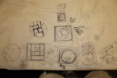
Photo fun
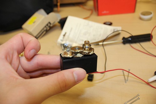
The gears inside the servo
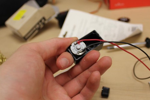
Making a servo spin continuously: remove the guts and solder power directly to the motor

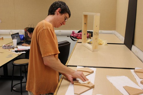
waxing the panels
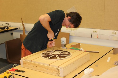
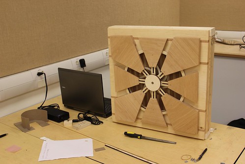
mounting the wheel
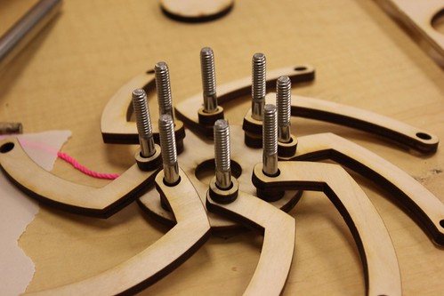
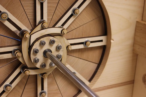
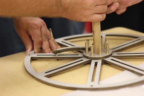
center spoke assembly
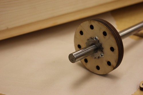
We used a spare gear to anchor the shaft to the hub
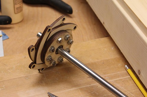
Hub assembled and the extra length on the bolts cut off
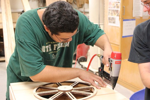
Adding a few more nails to the face plate
perfecting the tracks with a little filing
Fitting the front panels
Hub installed and the sliding panels connected
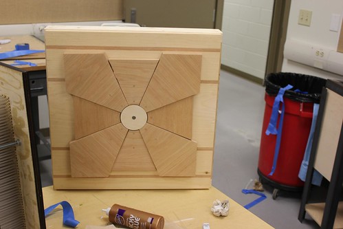
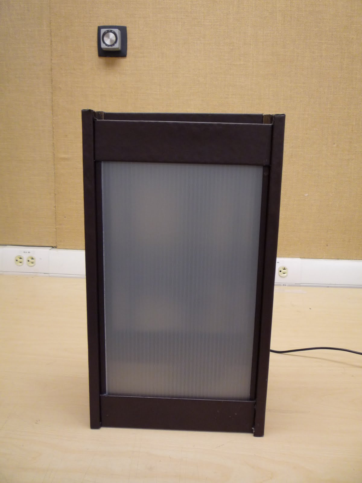
Closed
Open
Mounting the servo to the main shaft
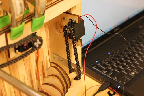
The modified servo connected to the wave machine cam shaft
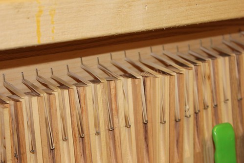
Rubber band ensure that wave machine paddles are always pressed against the cams
Concept
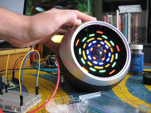
We started with the concept of an oculus that would open and close in response to some kind of human interaction. In researching precedents we found an expanding Jupe table by craftsman Theodore Alexander that expanded as it rotates. As we further developed the design we came up with a system that translates rotation into oscillation. This system can be seen as an example of the Coriolis Effect, a natural phenomenon that creates outward forces as a result of rotation. The most familiar examples being hurricanes, typhoons, or even the draining of a bath tub. By mounting the system on a track we are able to control the outward forces created by this phenomenon.

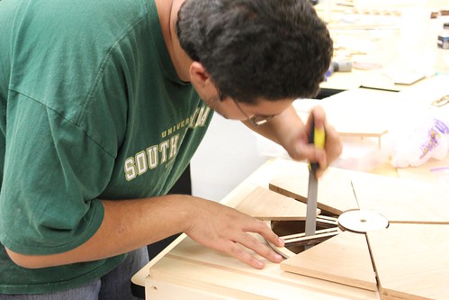
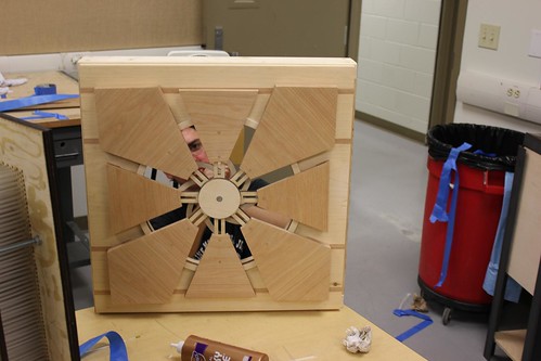
Using 8 wooden spades connected to a central track system, we were able to tie into a hub assembly using 8 radial arms cut out of ¼” plywood. The Radial arms are connected to the wooden spades using ¼” wood dowels allowing for pinned connections at either end, so, as the central hub assembly rotates, spun by a servo motor and chain drive, the spades move along the track system. The spade pieces were first laser cut out of 1/4" MDF to be used as a template. This template was then used to cut the spade out of the red oak using a bench router. Once all the spades were cut we gave them a finish sanding and sealed them with finishing wax.

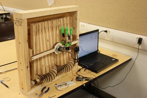
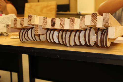
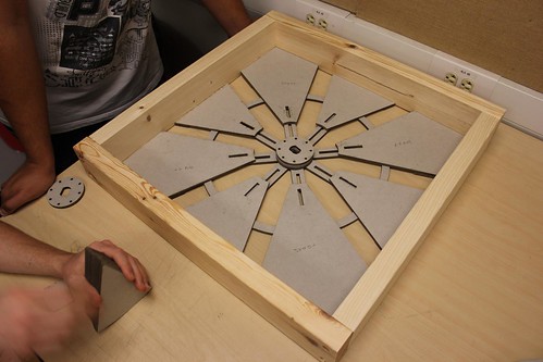
After designing the oculus we decided that there needed to be more happening in the background so we scoured the web and found an interesting double cam wave machine that was manually operated using two handles

Using this precedent we developed a single cam system that was connected to a modified servo motor which would run when the oculus was opened. The wave machine itself is a relatively simple construct. It is composed of 24 1”x2”x18” wood members (alternating red oak and pine) which are connected using a threaded rod that acts as a fulcrum. Groves are then cut into the bottom of each member to allow for the cam shaft to move smoothly. At the top of each member a rubber band is fitted in place so that each individual member will snap back into place once the cam lobe has passed it.
In order to make the project more interactive it needed to respond to the presence of the viewer so by installing an infrared proximity sensor we could detect if anyone was standing directly in front of it. We decided it would be fun to mess with people so the project was designed to be operating if no one was directly in front of it but once someone comes in for a closer look, the oculus would close and all motion would cease.

Using 8 wooden spades connected to a central track system, we were able to tie into a hub assembly using 8 radial arms cut out of ¼” plywood. The Radial arms are connected to the wooden spades using ¼” wood dowels allowing for pinned connections at either end, so, as the central hub assembly rotates, spun by a servo motor and chain drive, the spades move along the track system. The spade pieces were first laser cut out of 1/4" MDF to be used as a template. This template was then used to cut the spade out of the red oak using a bench router. Once all the spades were cut we gave them a finish sanding and sealed them with finishing wax.

After designing the oculus we decided that there needed to be more happening in the background so we scoured the web and found an interesting double cam wave machine that was manually operated using two handles
Using this precedent we developed a single cam system that was connected to a modified servo motor which would run when the oculus was opened. The wave machine itself is a relatively simple construct. It is composed of 24 1”x2”x18” wood members (alternating red oak and pine) which are connected using a threaded rod that acts as a fulcrum. Groves are then cut into the bottom of each member to allow for the cam shaft to move smoothly. At the top of each member a rubber band is fitted in place so that each individual member will snap back into place once the cam lobe has passed it.
In order to make the project more interactive it needed to respond to the presence of the viewer so by installing an infrared proximity sensor we could detect if anyone was standing directly in front of it. We decided it would be fun to mess with people so the project was designed to be operating if no one was directly in front of it but once someone comes in for a closer look, the oculus would close and all motion would cease.
Materials
1 Arduino Microcontroller
6 L.F. 1 x 12 Red Oak
12 L.F. 1 x 2 Red Oak
4 L.F. 1 x 12 Pine
12 L.F. 1 x 2 Pine
8 L.F. 2 x 4 Pine
1/8” Plywood - 4’ x 8’ Sheet
2 Hi Torque Digital Servo Motors
5/16” Threaded Rod - Approx 24”
2 EA. 5/16” Nuts and Washers
24 Rubber Bands
1/8” Wood Dowels
1/2” Diameter Soft Metal Rod
1/4” Drive Chain - Approx. 24”
1/2” Bearing
1/2” Sprocket (2 Ea.)
2 Straight Metal Brackets
Code
Here is how the arduino is currently setup:

Servo is in pin 9 and the proximity sensor in in analog pin 0.
Code:

Servo is in pin 9 and the proximity sensor in in analog pin 0.
Code:
#include <Servo.h>

#define proximityPin 0
#define maxCount 40

int proximity = 0;

Servo centerHub;  // create servo object to control a servo
                // a maximum of eight servo objects can be created

int pos = 0;    // variable to store the servo position

boolean state = true; //true = open, false = close
int count = 0;


void setup()
{
  centerHub.attach(9);
 // centerHub.write(0); //position 0 is all the way open
 Serial.begin(9600);
}


void loop()
{
  proximity = analogRead(proximityPin);
  Serial.println(proximity,DEC);
  //if some one is far away
  if(proximity < 100 && state == false){
    if(count > maxCount){
       //open
       for(pos = 180; pos>=1; pos-=1){
          centerHub.write(pos);
          delay(20);
        }
        delay(5000);
       state = true;
       count = 0;
    } else {
      count++;
    }
  }
  //if some ones comes close
  else if(proximity > 300 && state == true){
    if(count > maxCount){
       //close
      for(pos = 0; pos < 188; pos += 1) {
        centerHub.write(pos);
        delay(10);
      }
      delay(5000);
       state = false;
       count = 0;
    } else {

      count++;
    }
  }
  //if you are standing the middle
  else {
   count = 0;

  }
  delay(50);

}
Tuesday, July 20, 2010
Laser Cutting
One of the coolest things the USF School of Architecture has is a laser cutter.
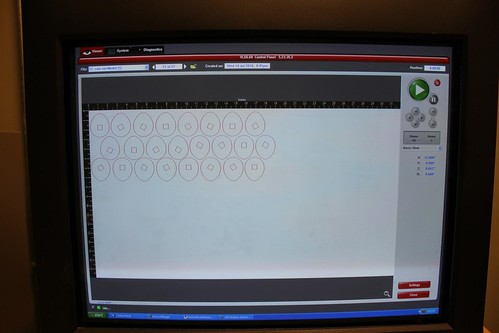
Cut marks are drawn in red in autocad and printed to the Versa Laser program
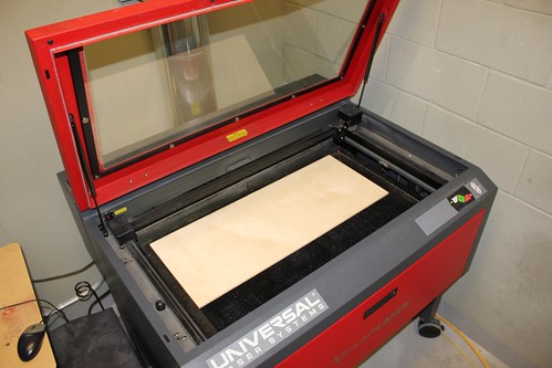
Load in material, quarter inch birch plywood
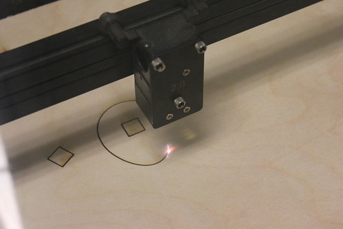
the laser cuts it perfectly

The pieces just needed a little push to fall out.
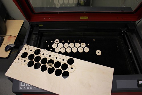
The parts assembled for the wave machine
Cut marks are drawn in red in autocad and printed to the Versa Laser program
Load in material, quarter inch birch plywood
the laser cuts it perfectly
The pieces just needed a little push to fall out.
The parts assembled for the wave machine
Tuesday, July 6, 2010
Marching towards the final
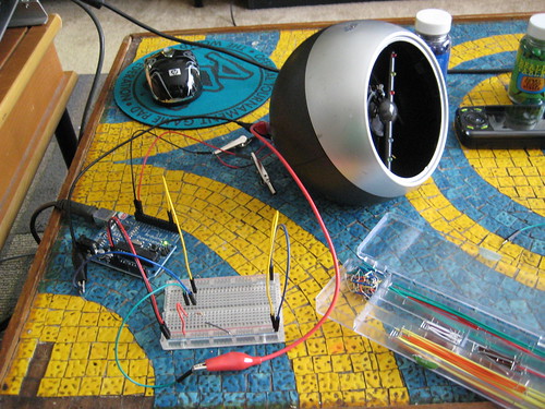
For the final, each group has a 2' square to use as a foundation to create some sort of interactive electronic demonstration
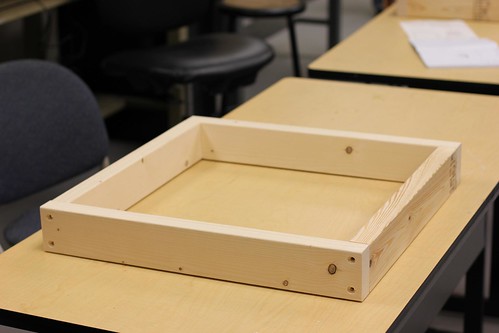
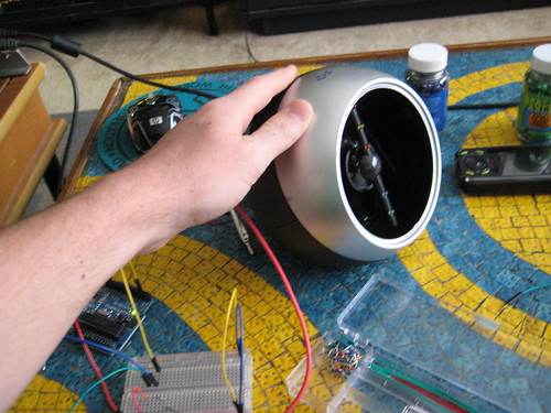
Our groups design is centered around a roating shaft that will slide panels open and close to reveal some sort of moving backdrop.
The shaft is going to be turned by 2 high torq servo link to the center shaft with gears. These parts will be delivered this week.
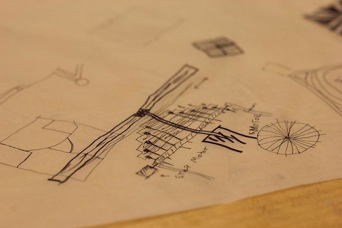
Currently the electronic design looks like:

For this project we are using a infrared proximity sensor connected to an arduino that will drive the servos. The mechanical design for the background is still being developed so this diagram may change.
More Photos
Our groups design is centered around a roating shaft that will slide panels open and close to reveal some sort of moving backdrop.
The shaft is going to be turned by 2 high torq servo link to the center shaft with gears. These parts will be delivered this week.
Currently the electronic design looks like:

For this project we are using a infrared proximity sensor connected to an arduino that will drive the servos. The mechanical design for the background is still being developed so this diagram may change.
More Photos
Tuesday, June 29, 2010
Hacking a Light Toy
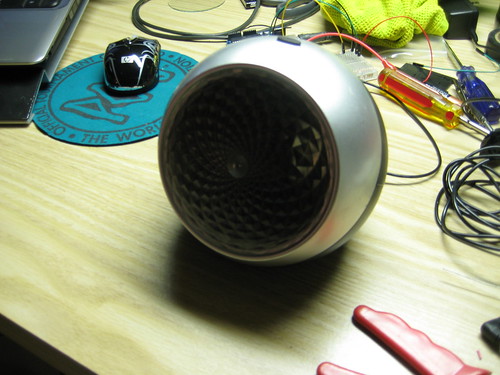
So after much frustration with my first attempt I decided to hack a toy instead of making something from scratch. The toy, shown below, just had a push button before, but I wanted to make it come on when the lights went off.

After breaking open the toy I popped out a piece from the back and slipped the wires out of the new hole.
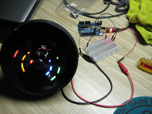
Before adding a sensor I wanted to make sure I could hack it and ran it with a simple blink code.
After doing this I was able to manipulate the function by making it strobe on and off. Success!

Now it's time for the photo resistor.
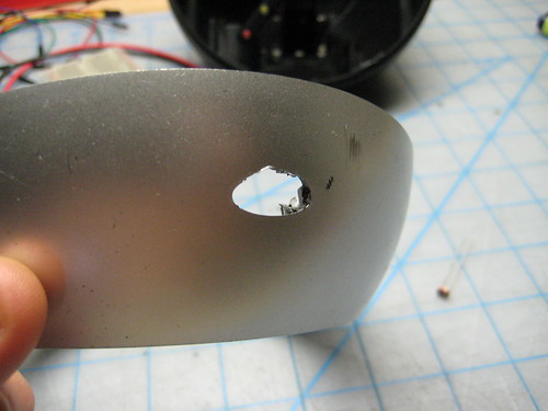
I removed the button to replace it with the photo resistor.

Set the resistor with hot glue.
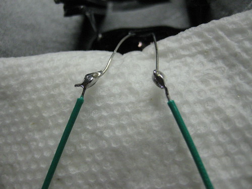
Solder some wires to it.
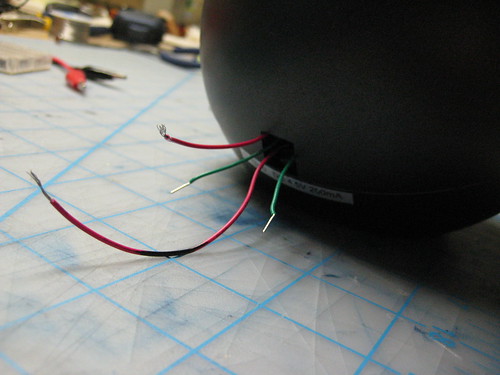
Pull out the wires.
Wire it up to the arduino.
Lights on...
Lights off...
The code I used is very simple. It's a combination of the example blink and button.
Here's the code:
/*
photo resistor as a Button
Turns on and off anything connected to digital
pin 13, when pressing a pushbutton attached to pin 2.
The circuit:
* LED attached from pin 13 to ground
* pushbutton attached to pin 2 from +5V
* 10K resistor attached to pin 2 from ground
* Note: on most Arduinos there is already an LED on the board
attached to pin 13.
created 2005
by DojoDave
modified 17 Jun 2009
by Tom Igoe
http://www.arduino.cc/en/Tutorial/Button
modified june 2010
by Richard Meacham
http://interactivesquared.blogspot.com/
*/
// constants won't change. They're used here to
// set pin numbers:
const int buttonPin = 2; // the number of the pushbutton pin
const int ledPin = 13; // the number of the LED pin
// variables will change:
int buttonState = 2000 ; // variable for reading the pushbutton status.
void setup() {
// initialize the LED pin as an output:
pinMode(ledPin, OUTPUT);
// initialize the pushbutton pin as an input:
pinMode(buttonPin, INPUT);
}
void loop(){
// read the state of the pushbutton value:
buttonState = digitalRead(buttonPin);
// check if the pushbutton is pressed.
// if it is, the buttonState is HIGH:
if (buttonState == HIGH) {
// turn LED on:
digitalWrite(ledPin, HIGH); // set the LED on
delay(500); // wait for a second
digitalWrite(ledPin, LOW); // set the LED off
delay(250); // wait for a second
}
else {
// turn LED off:
digitalWrite(ledPin, LOW);
}
}
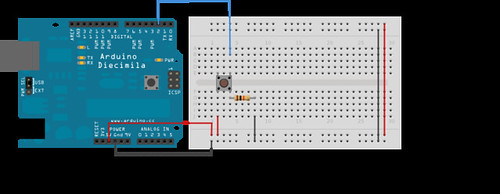
And the wiring diagram:
After breaking open the toy I popped out a piece from the back and slipped the wires out of the new hole.
Before adding a sensor I wanted to make sure I could hack it and ran it with a simple blink code.
After doing this I was able to manipulate the function by making it strobe on and off. Success!
Now it's time for the photo resistor.
I removed the button to replace it with the photo resistor.
Set the resistor with hot glue.
Solder some wires to it.
Pull out the wires.
Wire it up to the arduino.
Lights on...
Lights off...
The code I used is very simple. It's a combination of the example blink and button.
Here's the code:
/*
photo resistor as a Button
Turns on and off anything connected to digital
pin 13, when pressing a pushbutton attached to pin 2.
The circuit:
* LED attached from pin 13 to ground
* pushbutton attached to pin 2 from +5V
* 10K resistor attached to pin 2 from ground
* Note: on most Arduinos there is already an LED on the board
attached to pin 13.
created 2005
by DojoDave
modified 17 Jun 2009
by Tom Igoe
http://www.arduino.cc/en/Tutorial/Button
modified june 2010
by Richard Meacham
http://interactivesquared.blogspot.com/
*/
// constants won't change. They're used here to
// set pin numbers:
const int buttonPin = 2; // the number of the pushbutton pin
const int ledPin = 13; // the number of the LED pin
// variables will change:
int buttonState = 2000 ; // variable for reading the pushbutton status.
void setup() {
// initialize the LED pin as an output:
pinMode(ledPin, OUTPUT);
// initialize the pushbutton pin as an input:
pinMode(buttonPin, INPUT);
}
void loop(){
// read the state of the pushbutton value:
buttonState = digitalRead(buttonPin);
// check if the pushbutton is pressed.
// if it is, the buttonState is HIGH:
if (buttonState == HIGH) {
// turn LED on:
digitalWrite(ledPin, HIGH); // set the LED on
delay(500); // wait for a second
digitalWrite(ledPin, LOW); // set the LED off
delay(250); // wait for a second
}
else {
// turn LED off:
digitalWrite(ledPin, LOW);
}
}
And the wiring diagram:
Monday, June 21, 2010
Brain Storm
So I've been working on a list of ideas that I thought might be fun some better than others;
Board of balloons that inflate to reflect the location of a person
Series of fans that move to blow air away from people
Maybe we integrate the idea of a projected touchscreen with sound so that it projects an image on the floor and when you step in a certain area it produces some sort of sound
Some type of audio instructions that tell people how to interact with the project, then when they do it something happens
Some type of mirror mirror on the wall looking thing that begs to be freed from the "mirror prison" then when you touch it, it screams to leave it alone
Multitouch Surface
I've been looking at precedents for this final installation project and was intrigued by this multitouch surface. Its a little bit on the complicated side but I think we can do within our time constraints. Essentially it is a touchscreen that is attached to a computer in such a way that you dont need a mouse or keyboard. Check out the website below to see some of the applications.
Its an interesting project and has the potential to be extremely interactive but its also kind of boring in the sense that it is competely digital; It doesnt move, there arent any interesting mechanics or cool materials. Anyhow, check it out and let me know what you think. Also shoot any ideas you guys might have my way.
http://www.maximumpc.com/article/features/maximum_pc_builds_a_multitouch_surface_computer?page=0%2C0
Wednesday, June 16, 2010
Arduino Resources
Take a look at this video
Then take a look at this intro to coding [pdf]. It covers the basic of code well.
Next take a look over at adafruit's tutorial that walks through each line of the basic blink sketch.
Remember to have fun!
Then take a look at this intro to coding [pdf]. It covers the basic of code well.
Next take a look over at adafruit's tutorial that walks through each line of the basic blink sketch.
Remember to have fun!
The Idea
The Idea:
When we were introduced to this project as the "Lamp Monster" I knew I wanted my project to grow when it got angry, and what would piss you off more than getting electricuted by a battery? Essentially, what I came up with was a lamp fixture that opens up to reveal a smaller compartment which houses an LED light source. The LEDs are controlled using a photoresistor allowing for the lights to get brighter as the surrounding environment gets darker (and vise versa) While trying to figure out how to make this thing open and close I considered small gear system attached to a servo motor or a some kind of pully system but it seemed overly complicated for such a simple function. After discussing the project with my brother, a mechanic, we determined that this process could be simplified by using a window motor and regulator assembly from a car.
The Materials:
- Arduino Microcontroller
- Auto Window Motor and Regulator Assembly
- 10 LEDs
- 12v battery
- Photoresistor
- 10k Ohm resistor
- Up/Down toggle switch
- 18 ga. wire for motor
- 24 ga. wire for lights
- Two 1/4" x 1" machine bolts
- Two 1/4" x 1" coupling nuts
- Two 1/4" x 1" washers
- Approx. 3 sheets of 28" x 40" double ply chip board
Step One:
The first step to contructing this project was building a case that would house the motor and regulator. The housing is composed of two pieces, a main lower case where the motor and regulator will be mounted and an upper light compartment that will be pushed and pulled by the motor. Using a laser cutter and some chip board I cut out the individual pieces for the vertical and horizontal supports, then laminated those pieces until they were four plies thick. Once the glue had cured I assembled the upper and lower portions seperately. On the lower portion of the case I located the mounting studs on the horizontal bracing and driled 1/4" holes for the machine bolts. After attaching the coupling nuts to the mounting studs on the regulator I attached the entire assembly to the lower portion of my case.

Step Two:
Now that the motor and regulator assembly were in place I can wire in the switch. Initially, I wanted to have the motor controlled by the arduino board using a proximity sensor (if you got within five feet it would open up otherwise it would close) but I ran into some trouble because the window motor is multidirectional. Whether the motor moves up or down depends on the direction in which the current is flowing. I was able to give dedicated power and ground through the arduino, but I could not figure out how to switch between the two. I hope to revisit this with some assistance but eventually, I ended up using a two way up/down switch to control motion.

Using the two way switch allowed me to reverse the flow of current at will, but the wiring was a little weird. The two center leads go to the main power and ground source. The top and bottom leads are then crossed and spliced (ie. top left and bottom right leads are wired seperately and then spliced together. 2 input, 1 output). Now there are a total of four wires the two from the center that will connect to the battery and the two top and bottom wires that will connect to the motor. The wiring is a little unrefined at the moment but once everything is connected you should be able to move the motor using the switch.
Step Three:
Once the motor was in place and operational I created two light bars using five LED's each. The LED's were wired in series so they would terminate in a single positive and single negative lead per light bar. I made sure to leave enough extra wire as these light bars will be attached to the upper portion of the case and will be moving up and down roughly 12". One of the problems I had once the LEDs were installed was controlling the brightness. I felt as though the lights were underpowered and were not shining as brightly as they could.

Step Four:
Now that the wiring was pretty much complete I created two face plates one for the upper and lower case. I created a simple face plate using some basswood and corrugated plastic but you can use any number of materials and turn it into a type of infill excercise. I plan on playing around with this part alot more.

Step Five:
Now that everything has been assembled I created the following circuit to controll the LEDS through the Arduino board using a photosensor.
- LED 1 and LED 2 connected from digital pin 9 to ground
- Photoresistor attached from analog pin 0 to ground
- 10k ohm resistor attached from analog pin 0 to ground

Step Six:
Once the circuit has been created I used the following code to control the lights
//Program to control LED through Photoresistor
//brightness specified by the value of the analog input
// as the environnment gets darker the LEDs get brighter
int val = 0; // variable used to store the value coming from the sensor
int LED = 9; // defines digital pin 9 as LED
void setup() {
pinMode(LED, OUTPUT); // defines LED pin as output
}
void loop() {
val = analogRead(0);// read the value from the sensor
analogeWrite(LED, 15000/val); //makes brightness of LED dependant on analog input
// as "val" increases power output decreases
delay(10); // stops the program for a period of time
}
This code worked pretty well but there were a couple things I couldnt figure out. I wanted to install a button so that when the lamp was fully open it would hold this button and initiate the lights until it is let go however I couldnt get the button to work with the photosensor the way I wanted it to. In the end I eliminated the button for the sake of time but it is something I hope to revisit with some assistance.

Subscribe to:
Posts (Atom)