Monday, July 26, 2010
Thursday, July 22, 2010
Photo fun
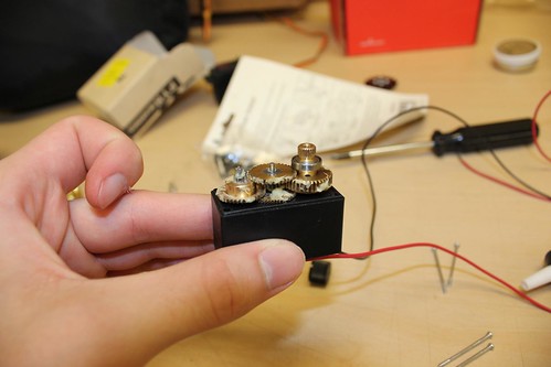
The gears inside the servo
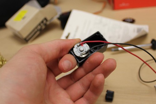
Making a servo spin continuously: remove the guts and solder power directly to the motor
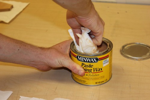
waxing the panels
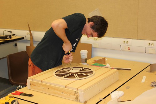
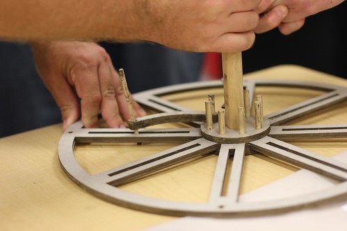
mounting the wheel
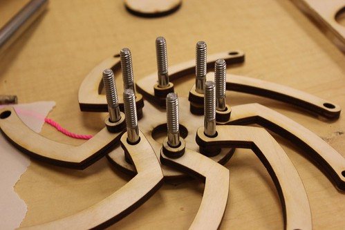
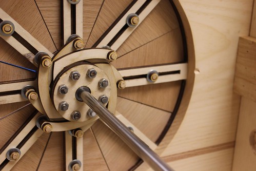
center spoke assembly
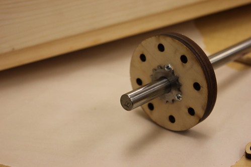
We used a spare gear to anchor the shaft to the hub
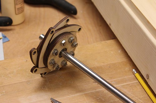
Hub assembled and the extra length on the bolts cut off
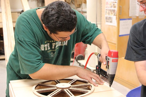
Adding a few more nails to the face plate
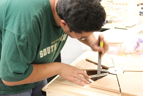
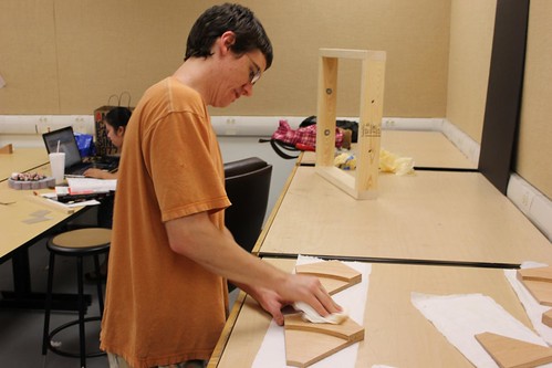
perfecting the tracks with a little filing
Fitting the front panels
Hub installed and the sliding panels connected
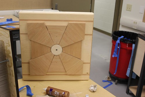
Closed
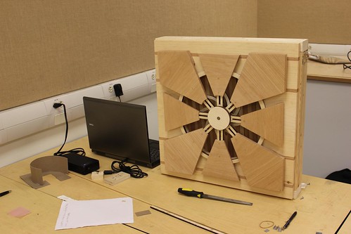
Open
Mounting the servo to the main shaft
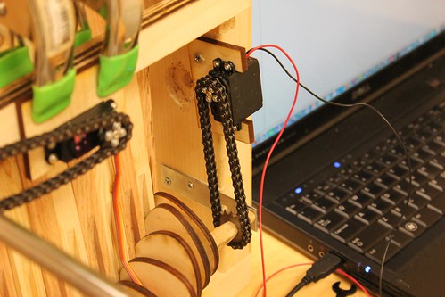
The modified servo connected to the wave machine cam shaft
Rubber band ensure that wave machine paddles are always pressed against the cams
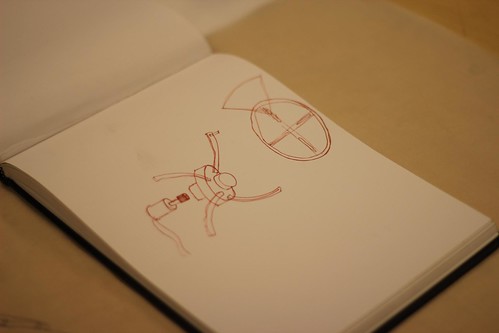
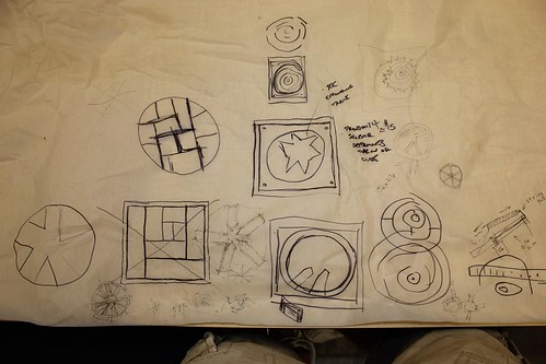
Concept
We started with the concept of an oculus that would open and close in response to some kind of human interaction. In researching precedents we found an expanding Jupe table by craftsman Theodore Alexander that expanded as it rotates. As we further developed the design we came up with a system that translates rotation into oscillation. This system can be seen as an example of the Coriolis Effect, a natural phenomenon that creates outward forces as a result of rotation. The most familiar examples being hurricanes, typhoons, or even the draining of a bath tub. By mounting the system on a track we are able to control the outward forces created by this phenomenon.

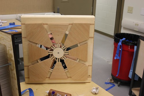
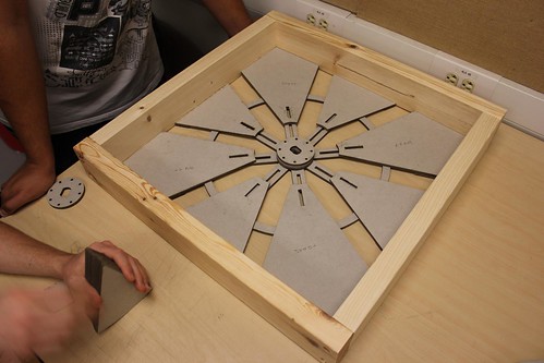
Using 8 wooden spades connected to a central track system, we were able to tie into a hub assembly using 8 radial arms cut out of ¼” plywood. The Radial arms are connected to the wooden spades using ¼” wood dowels allowing for pinned connections at either end, so, as the central hub assembly rotates, spun by a servo motor and chain drive, the spades move along the track system. The spade pieces were first laser cut out of 1/4" MDF to be used as a template. This template was then used to cut the spade out of the red oak using a bench router. Once all the spades were cut we gave them a finish sanding and sealed them with finishing wax.

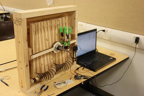
After designing the oculus we decided that there needed to be more happening in the background so we scoured the web and found an interesting double cam wave machine that was manually operated using two handles

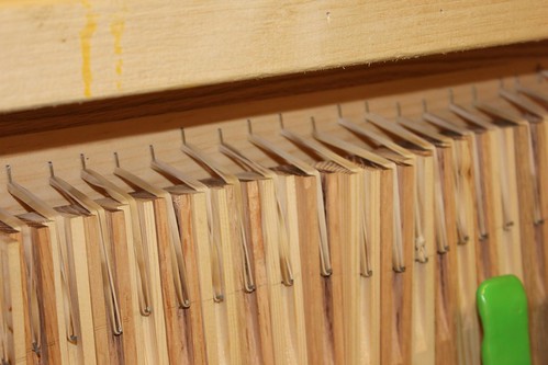
Using this precedent we developed a single cam system that was connected to a modified servo motor which would run when the oculus was opened. The wave machine itself is a relatively simple construct. It is composed of 24 1”x2”x18” wood members (alternating red oak and pine) which are connected using a threaded rod that acts as a fulcrum. Groves are then cut into the bottom of each member to allow for the cam shaft to move smoothly. At the top of each member a rubber band is fitted in place so that each individual member will snap back into place once the cam lobe has passed it.
In order to make the project more interactive it needed to respond to the presence of the viewer so by installing an infrared proximity sensor we could detect if anyone was standing directly in front of it. We decided it would be fun to mess with people so the project was designed to be operating if no one was directly in front of it but once someone comes in for a closer look, the oculus would close and all motion would cease.

Using 8 wooden spades connected to a central track system, we were able to tie into a hub assembly using 8 radial arms cut out of ¼” plywood. The Radial arms are connected to the wooden spades using ¼” wood dowels allowing for pinned connections at either end, so, as the central hub assembly rotates, spun by a servo motor and chain drive, the spades move along the track system. The spade pieces were first laser cut out of 1/4" MDF to be used as a template. This template was then used to cut the spade out of the red oak using a bench router. Once all the spades were cut we gave them a finish sanding and sealed them with finishing wax.

After designing the oculus we decided that there needed to be more happening in the background so we scoured the web and found an interesting double cam wave machine that was manually operated using two handles
Using this precedent we developed a single cam system that was connected to a modified servo motor which would run when the oculus was opened. The wave machine itself is a relatively simple construct. It is composed of 24 1”x2”x18” wood members (alternating red oak and pine) which are connected using a threaded rod that acts as a fulcrum. Groves are then cut into the bottom of each member to allow for the cam shaft to move smoothly. At the top of each member a rubber band is fitted in place so that each individual member will snap back into place once the cam lobe has passed it.
In order to make the project more interactive it needed to respond to the presence of the viewer so by installing an infrared proximity sensor we could detect if anyone was standing directly in front of it. We decided it would be fun to mess with people so the project was designed to be operating if no one was directly in front of it but once someone comes in for a closer look, the oculus would close and all motion would cease.
Materials
1 Arduino Microcontroller
6 L.F. 1 x 12 Red Oak
12 L.F. 1 x 2 Red Oak
4 L.F. 1 x 12 Pine
12 L.F. 1 x 2 Pine
8 L.F. 2 x 4 Pine
1/8” Plywood - 4’ x 8’ Sheet
2 Hi Torque Digital Servo Motors
5/16” Threaded Rod - Approx 24”
2 EA. 5/16” Nuts and Washers
24 Rubber Bands
1/8” Wood Dowels
1/2” Diameter Soft Metal Rod
1/4” Drive Chain - Approx. 24”
1/2” Bearing
1/2” Sprocket (2 Ea.)
2 Straight Metal Brackets
Code
Here is how the arduino is currently setup:

Servo is in pin 9 and the proximity sensor in in analog pin 0.
Code:

Servo is in pin 9 and the proximity sensor in in analog pin 0.
Code:
#include <Servo.h>

#define proximityPin 0
#define maxCount 40

int proximity = 0;

Servo centerHub;  // create servo object to control a servo
                // a maximum of eight servo objects can be created

int pos = 0;    // variable to store the servo position

boolean state = true; //true = open, false = close
int count = 0;


void setup()
{
  centerHub.attach(9);
 // centerHub.write(0); //position 0 is all the way open
 Serial.begin(9600);
}


void loop()
{
  proximity = analogRead(proximityPin);
  Serial.println(proximity,DEC);
  //if some one is far away
  if(proximity < 100 && state == false){
    if(count > maxCount){
       //open
       for(pos = 180; pos>=1; pos-=1){
          centerHub.write(pos);
          delay(20);
        }
        delay(5000);
       state = true;
       count = 0;
    } else {
      count++;
    }
  }
  //if some ones comes close
  else if(proximity > 300 && state == true){
    if(count > maxCount){
       //close
      for(pos = 0; pos < 188; pos += 1) {
        centerHub.write(pos);
        delay(10);
      }
      delay(5000);
       state = false;
       count = 0;
    } else {

      count++;
    }
  }
  //if you are standing the middle
  else {
   count = 0;

  }
  delay(50);

}
Tuesday, July 20, 2010
Laser Cutting
One of the coolest things the USF School of Architecture has is a laser cutter.
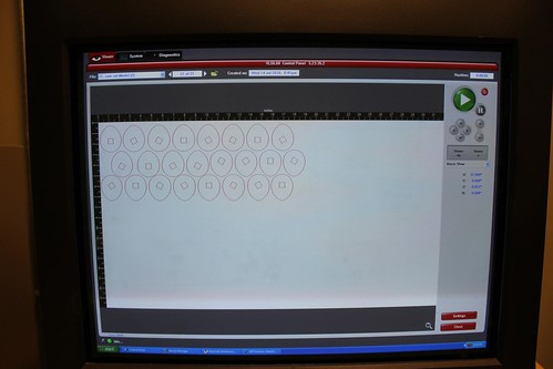
Cut marks are drawn in red in autocad and printed to the Versa Laser program
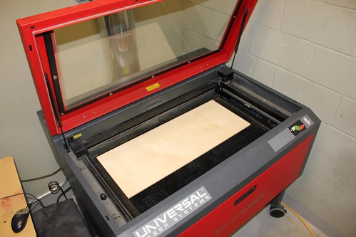
Load in material, quarter inch birch plywood
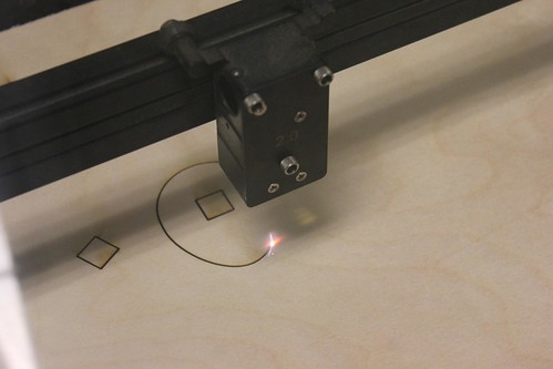
the laser cuts it perfectly

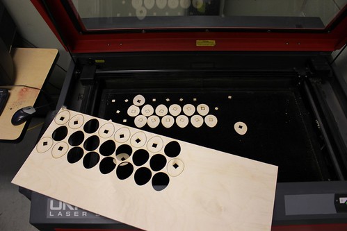
The pieces just needed a little push to fall out.
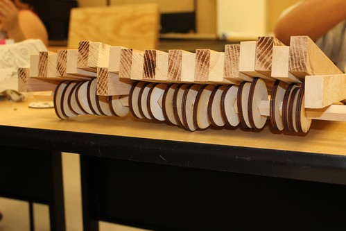
The parts assembled for the wave machine
Cut marks are drawn in red in autocad and printed to the Versa Laser program
Load in material, quarter inch birch plywood
the laser cuts it perfectly
The pieces just needed a little push to fall out.
The parts assembled for the wave machine
Tuesday, July 6, 2010
Marching towards the final
For the final, each group has a 2' square to use as a foundation to create some sort of interactive electronic demonstration
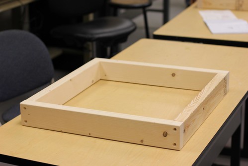
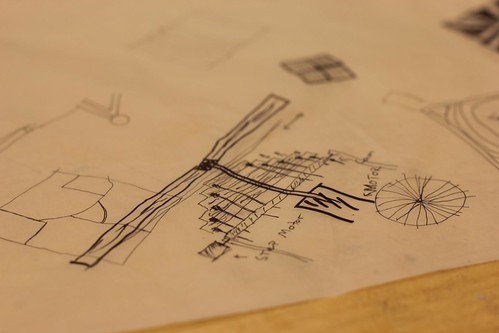
Our groups design is centered around a roating shaft that will slide panels open and close to reveal some sort of moving backdrop.
The shaft is going to be turned by 2 high torq servo link to the center shaft with gears. These parts will be delivered this week.
Currently the electronic design looks like:

For this project we are using a infrared proximity sensor connected to an arduino that will drive the servos. The mechanical design for the background is still being developed so this diagram may change.
More Photos
Subscribe to:
Posts (Atom)